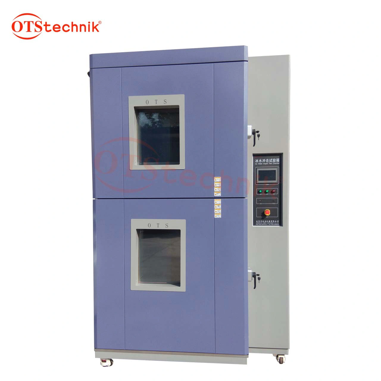
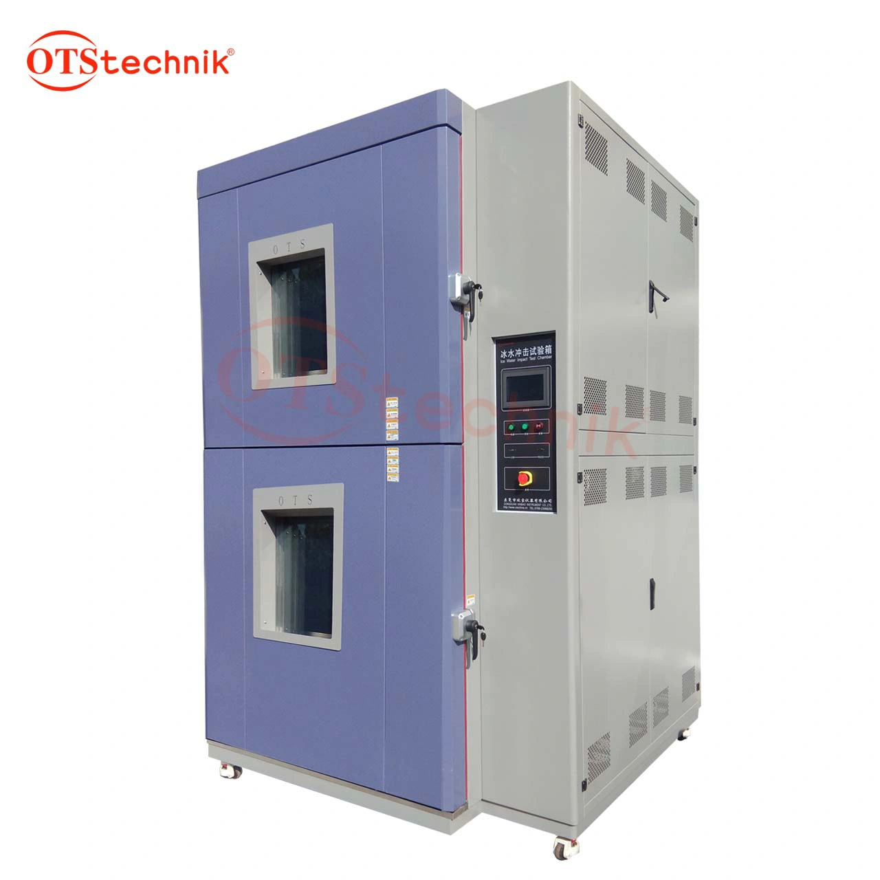
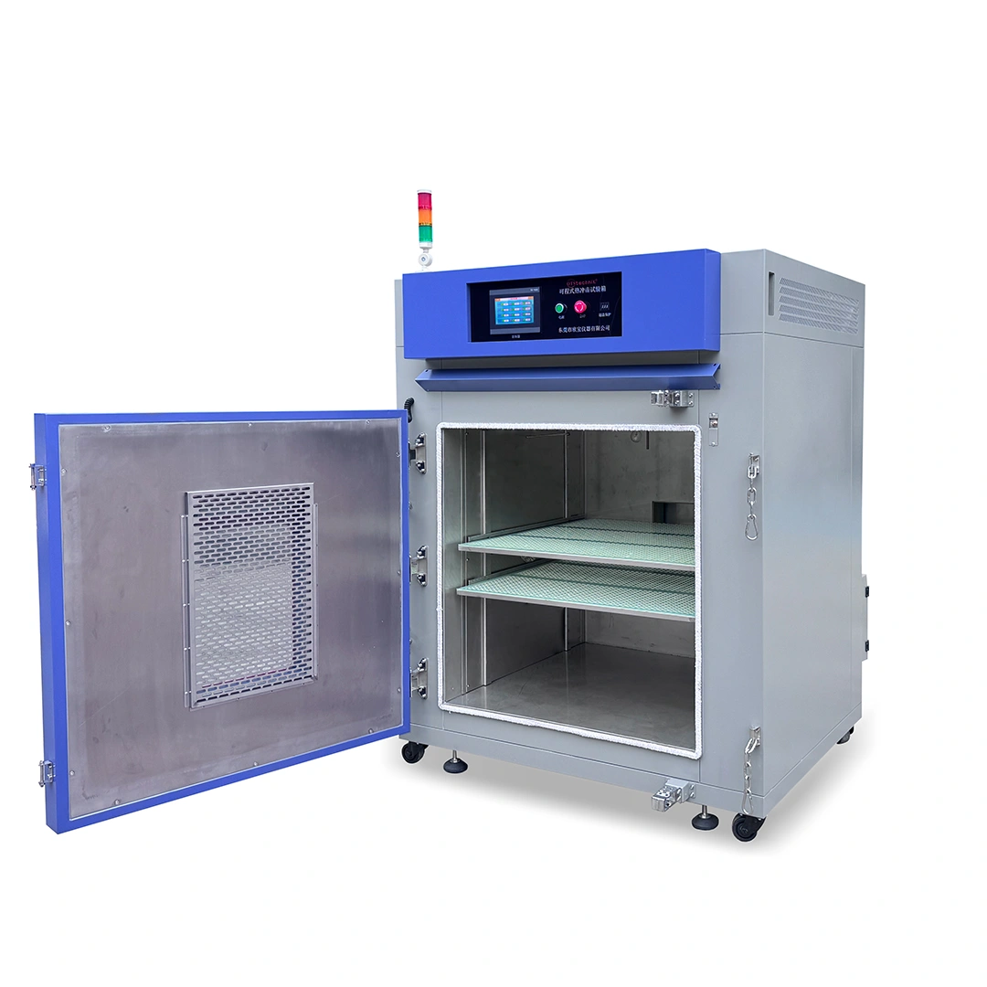
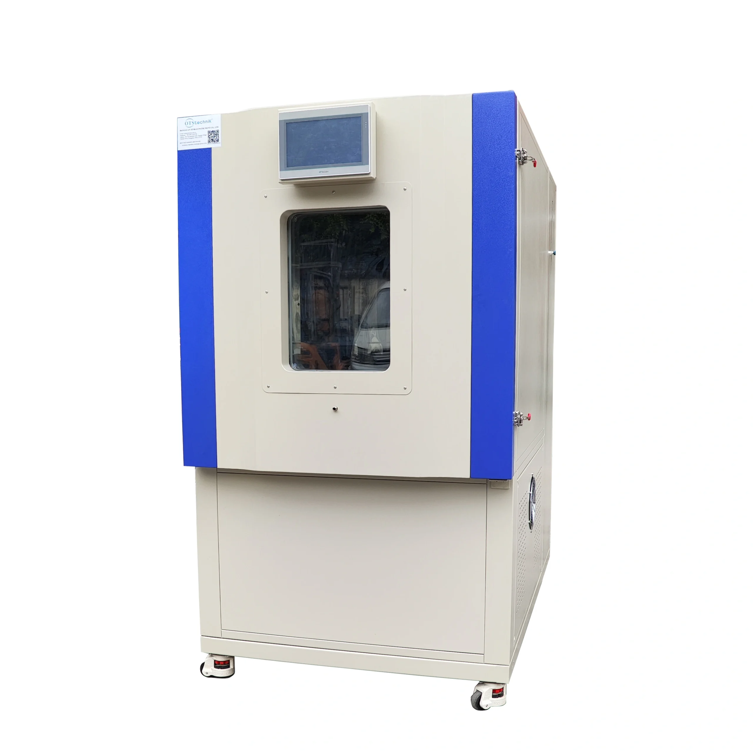
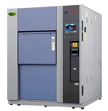
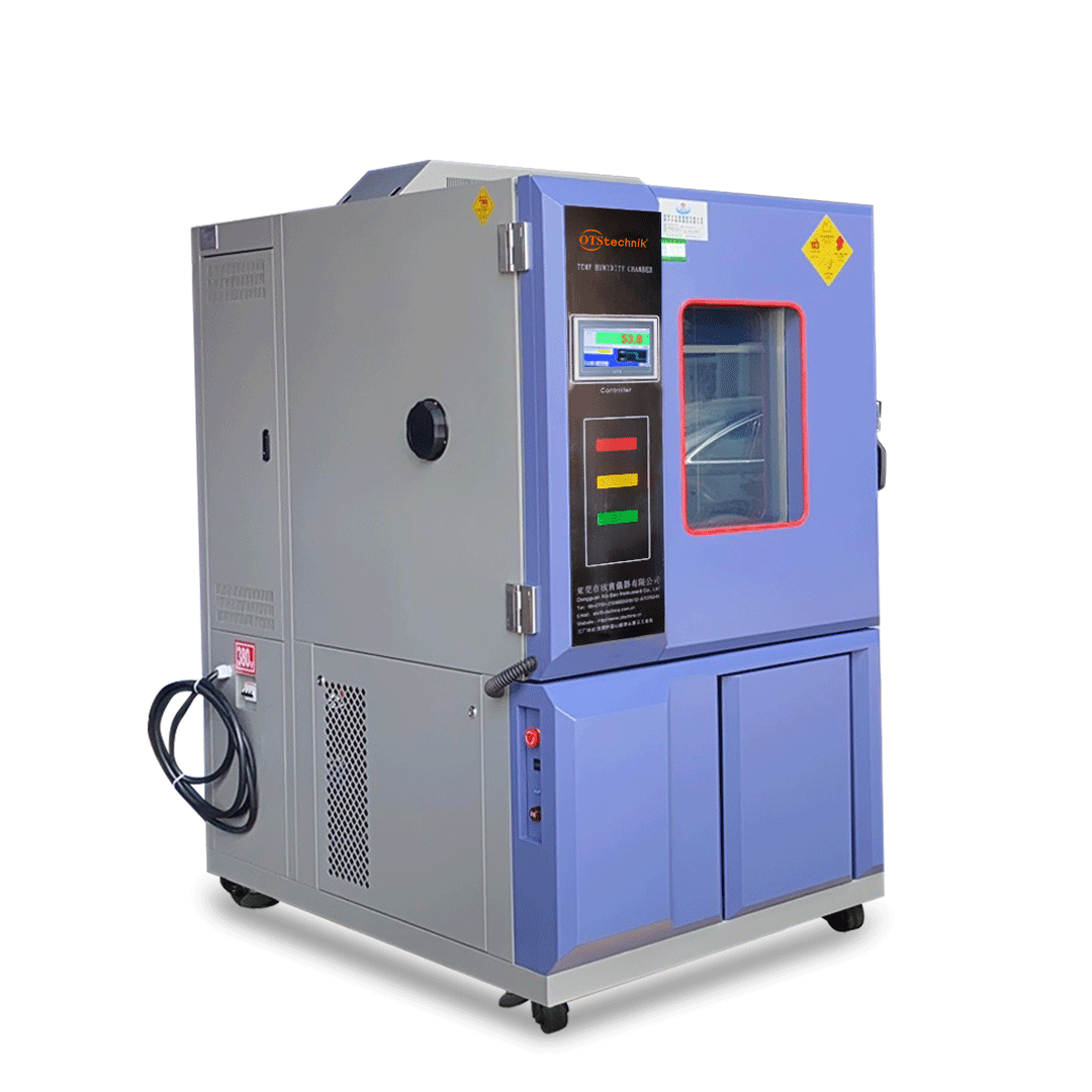
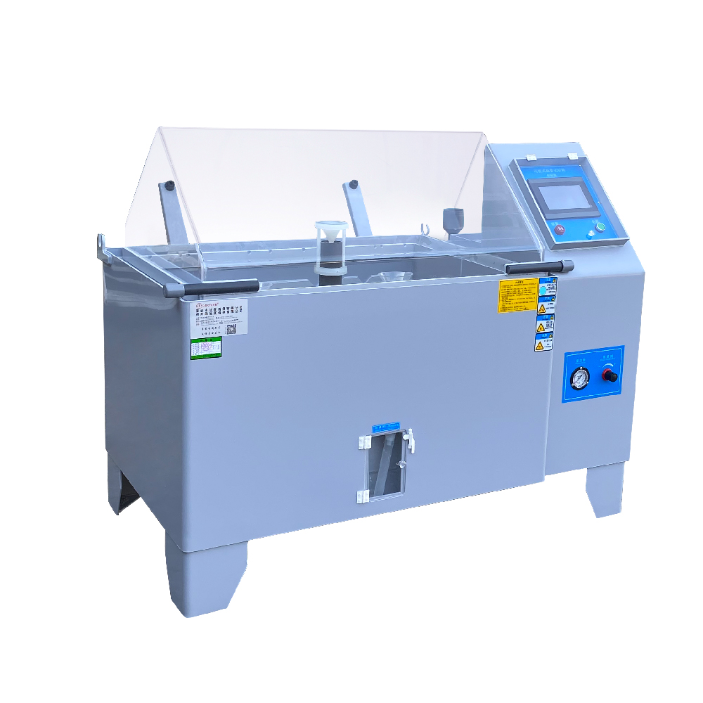
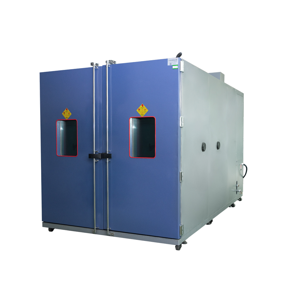
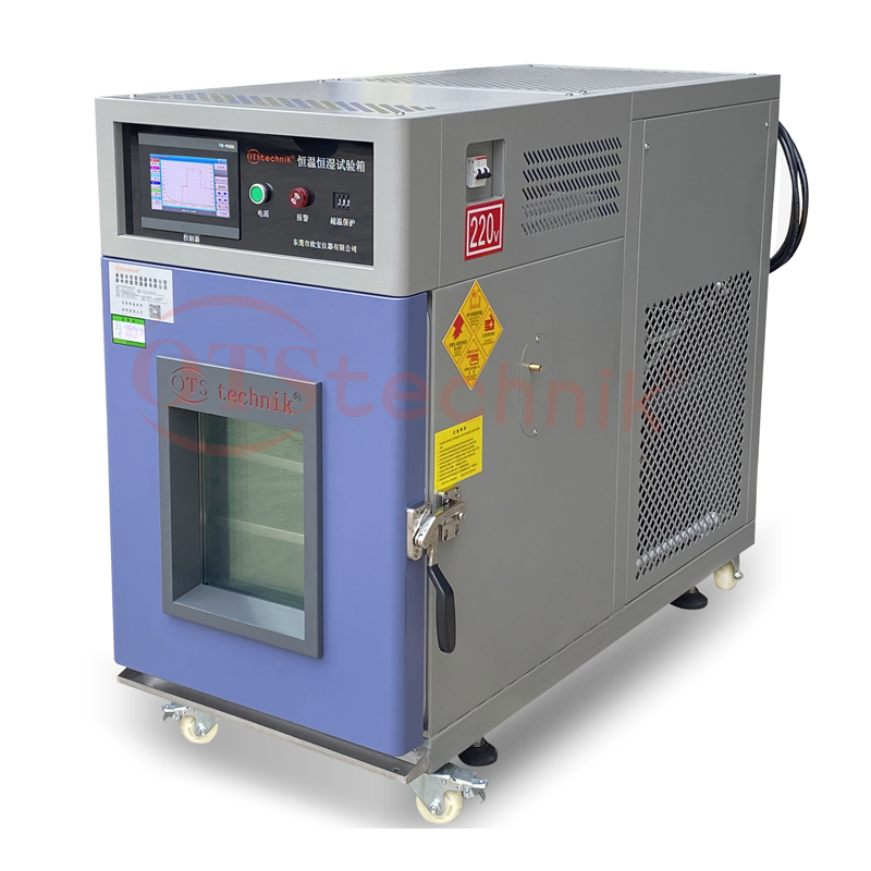
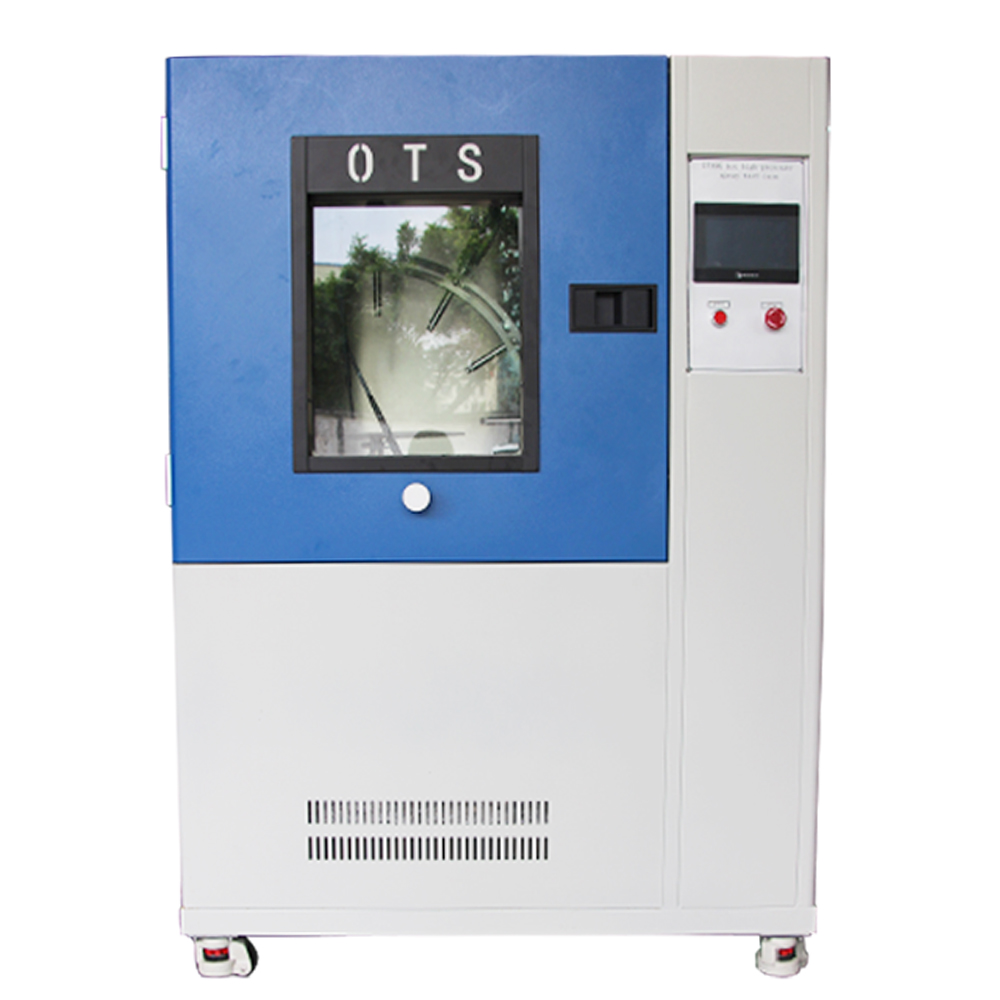
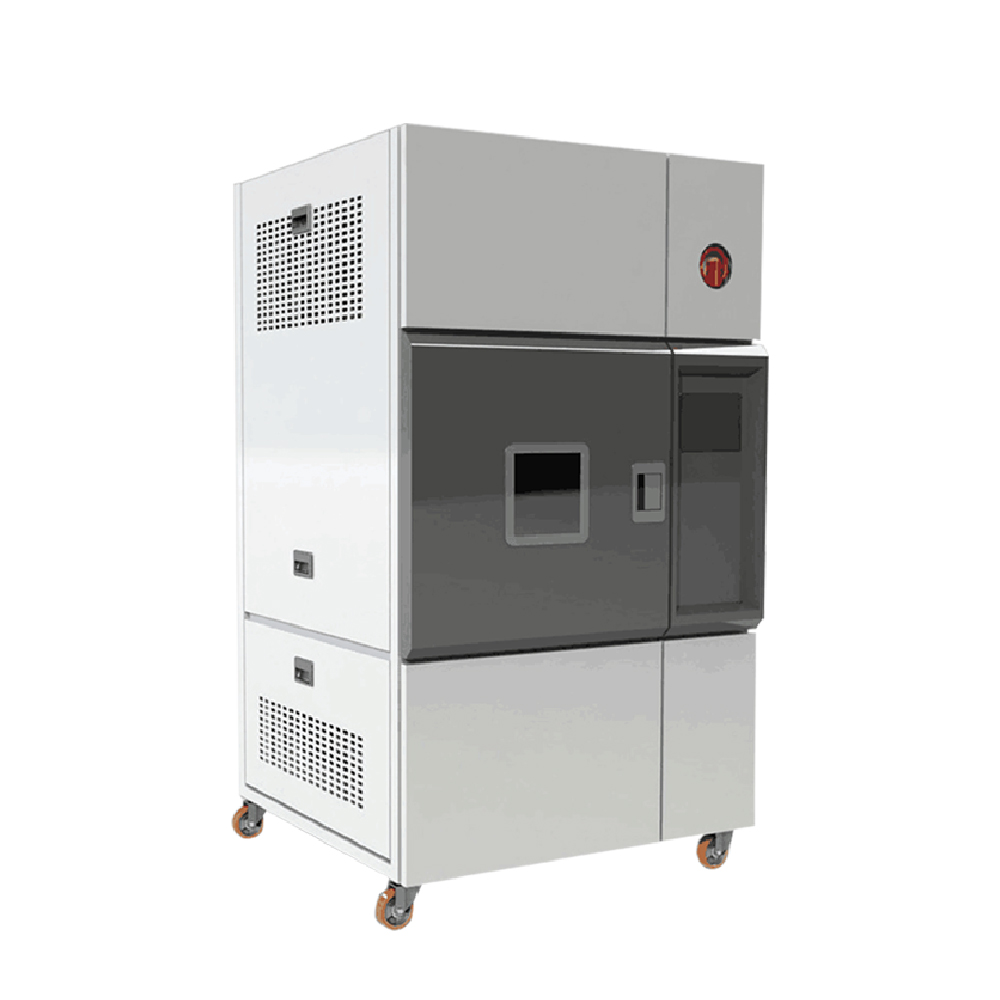
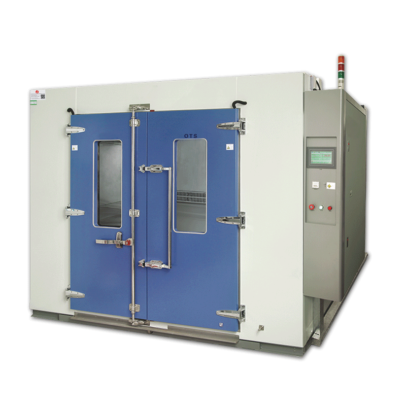
Function of Liquid Thermal Shock Chamber
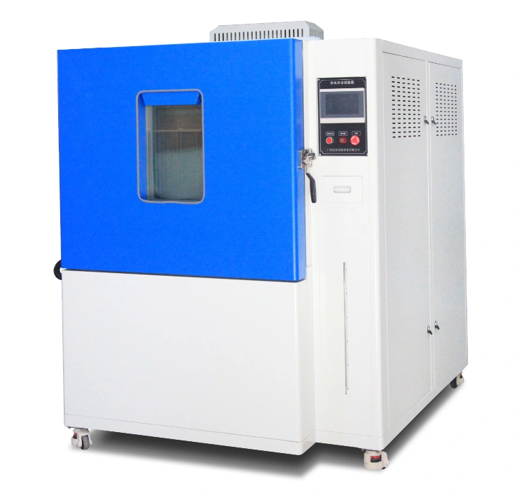
The liquid thermal shock test chamber can perform splashing or high-temperature tests alone, simulating ice water splashing onto the heating system or components when driving on wet roads in winter. The failure mode is mechanical cracking of the material or sealing failure caused by different temperature expansion coefficients. The liquid thermal shock test chamber is a reliability test equipment for heat and cold resistance, ice water splashing test, and quality control engineering of various raw materials and devices such as electronics, electrical engineering, electrical appliances, and plastics.
Liquid Thermal Shock Chamber is mainly used in the automotive industry, including:
- Evaluating automotive parts’ thermal durability, such as engine components, sensors, and control modules.
- Simulating the extreme temperature changes that vehicles may encounter in different environments.
Standard Compliance
GB/T 28046.4-2011 (ISO 16750-4:2006): Environmental Conditions and Tests for Electrical and Electronic Equipment of Road Vehicles Part 4: Climatic Load
VW80000: 2009-10 LV124 Test Items, Test Conditions and Test Requirements for Electrical and Electronic Components of Vehicles Less than 3.5 Tons.
Liquid Thermal Shock Chamber Specification
| Model | XB-OTS-150V-A | XB-OTS-384V-A | XB-OTS-800V-A |
|---|---|---|---|
| Water Tank Size | 200L with stirrer, size can be customized | ||
| Inner Size WDH | 60*50*50cm | 80*60*80cm | 100*80*100cm |
| External Size WDH | 160*220*150cm | 180*240*180cm | 200*285*180cm |
| Temperature Range | RT+10℃~150℃ | ||
| Test Medium Display Accuracy | 0.01℃ | ||
| Test Medium Stability | ≦±2℃ | ||
| Test Liquid Medium | Deionized water or+3% Arizona fine dust | ||
| Water Temperature Range | (0~+4)℃ | ||
| Water Temp Stability | ≦±0.5℃ | ||
| Water Temp Fluctuation | ≦±2℃ | ||
| Heating Rate | RT+10℃~150℃≤45min | ||
| Cooling Rate | 25℃~2℃≤60min | ||
| Number Of Orifices | 1 slit nozzle | ||
| Orifice Position | Right side of inner chamber | ||
| Distance Between Nozzle And Sample | 325 ± 25mm (adjustable manually) | ||
| Injection Time Per Cycle (30min) | 3S, interval time: 29m57s (touch screen setting) | ||
| Number Of Cycles | 100 times (touch screen setting) | ||
| Water Spray Flow | (3~4)L/3S | ||
| Power Supply | 3phase 380V 50Hz or customized | ||
| Power | 12.0KW | ||
| Safety Protection Function | Leakage protection, short circuit protection, water shortage protection, thermal overload protection, phase sequence protection | ||
| Accessories | One copy of operation manual; One copy of factory certificate; One copy of equipment warranty card; Water pipe 6m (1 piece) |
||
| Use Conditions | The user guarantees the following conditions and completes the corresponding connection | ||
| Use Site | 1. The ground and wall are flat and waterproof, the drainage is smooth, and the floor drain or drainage ditch is set; 2. The ground bearing capacity is not less than 200kg/m2; 3. The site is well ventilated; 4. No strong vibration around the equipment; 5. There is no strong electromagnetic field around the equipment; 6. There are no flammable, explosive, corrosive substances and dust around the equipment; 7. Proper use and maintenance space shall be reserved around the equipment: rear side, left and right sides, top: 800mm; Front side of equipment: 1500mm. |
||
| Environment Condition | Temperature:5℃~35℃ Humidity:≤85% Are pressure:86kPa~106kPa |
||
| Grounding resistance of protective ground wire | The grounding resistance of protective ground wire is less than 4 Ω | ||
| Power switch | 1. The user needs to configure a leakage protection air switch of corresponding capacity for the equipment at the installation site, and the switch must be used independently for the equipment; 2. Do not use knife switch or power socket; 3. The position of leakage protection air switch not more than 2m away from the equipment. |
||
| Water source conditions | 1. The user is required to provide water for the equipment at the installation site, with the water pressure not less than 0.2Mpa, and install a four tap. 2. The water tap shall not be more than 2m away from the equipment |
||
Controller of Liquid Thermal Shock Chamber
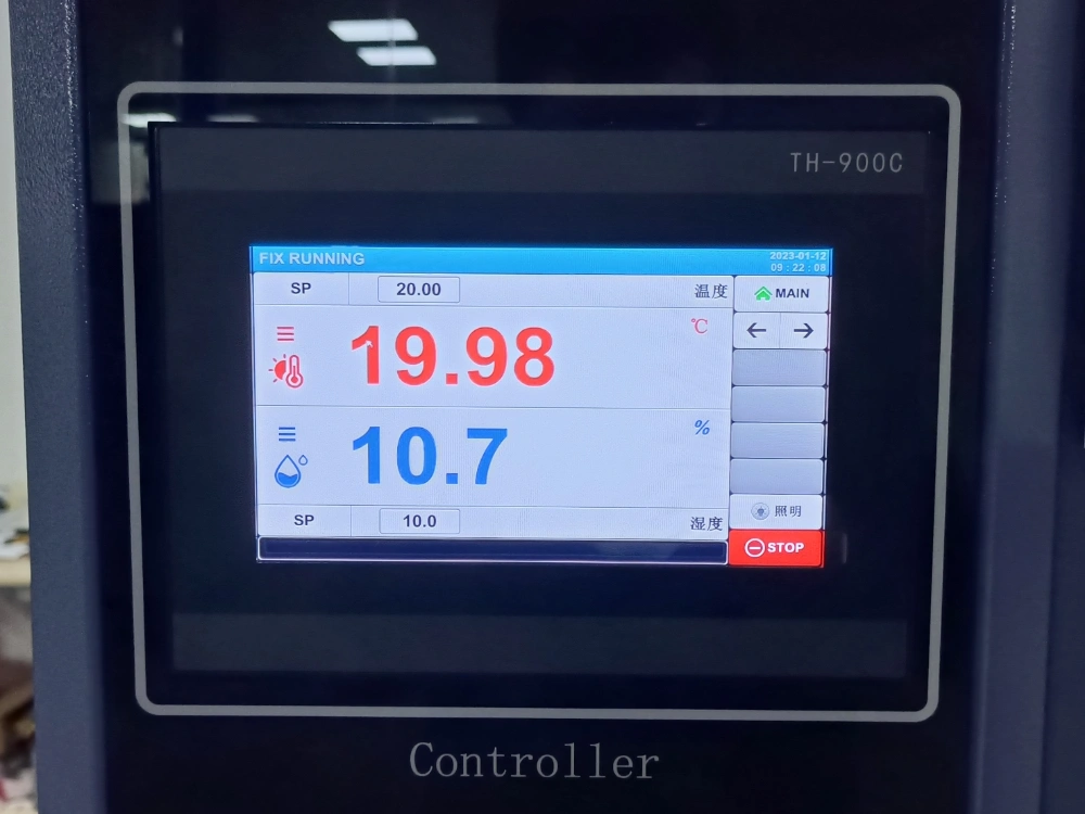
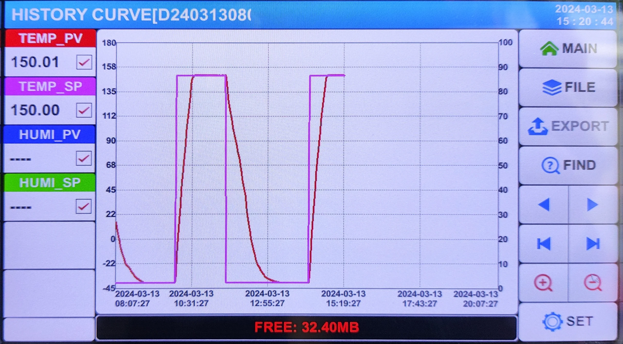
| Screen Size & Display | 7″ TFT-LCD |
|---|---|
| Download data | By USB directly |
| Language | ENG (other languages can be acceptable) |
| Number of Program Groups | 120 Groups, each Group with 1200 segments with 9999 cycles |
| Connected to PC | YES |
| Easy for Operation | YES |
Structure of Liquid Thermal Shock Chamber
Unique refrigerant servo valve flow control. Power saving is more than 30%; with the United States PWM combination design and low-temperature working conditions, the heater does not participate in the work through the PWM technology to control the refrigeration unit refrigerant flow and flow. Through the pipeline, a hot bypass pipe three-way flow adjustment is made to achieve the studio temperature automatically being constant. This way, in low-temperature conditions, a 30% reduction in energy consumption can be achieved, and the machine power control is 8.5KW or less.
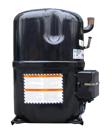
- Imported Compressor
- Fits a wide range of pressure
- Higher heating efficiency
- Easy to maintain
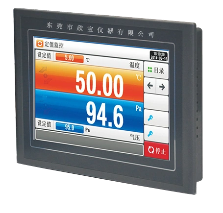
- Controller Interface
- LED Touch Screen
- Equipped with 127 programme
- Built-in large storage data Automatic brightness control
- Touch interactive parameter input
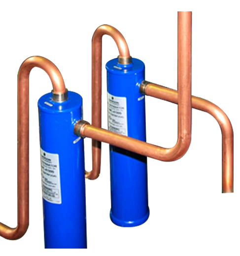
- Advanced united bend pipe technology
- Corrosion resistant
- High purity
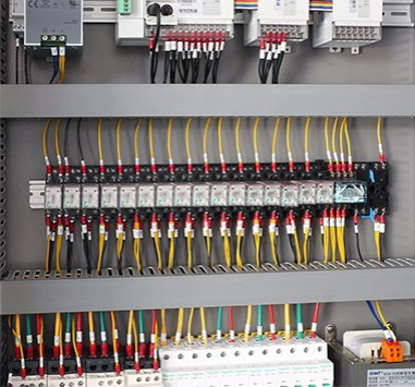
- Reasonable circuit design
- It applies to the ice water splash resistance test of the product
- The shell is formed by a domestic high-quality steel plate CNC machine tool, and the surface is sprayed with baking paint, which is beautiful and durable.
- The inner box is made of a SUS304 # stainless steel plate to ensure no rust after long-term use.
- Thermal insulation material: high-density glass fiber cotton to ensure thermal insulation performance and maintain a balanced and stable indoor temperature.
- The door is equipped with a transparent observation window (multi-layer hollow tempered glass) and an LED lighting lamp to observe the internal test conditions.
- The mixing system uses a long shaft fan motor and 304 stainless steel multi-wing impeller with high and low-temperature resistance to achieve vertical diffusion circulation of intensive convection to make the temperature in the laboratory uniform and stable.
- The test hole (100mm in diameter) is installed on the left side of the equipment, which can be externally connected to the test power line or signal line.
- The equipment control part is designed on the right side of the equipment, with control touch screen, control switch, etc., which is easy to operate and maintain;
- High-quality fixed PU movable Korean casters are installed at the bottom of the machine, which can easily move the machine to the specified position and finally fix the casters.
- The control system uses a 7-inch touch screen+Panasonic PLC. The electrical components are imported brands such as LS, Omron, etc. The wiring process meets the requirements of national standards. The electrical board layout is reasonable, the wiring is firm, and the markings are clear.
- The 7-inch LCD touchscreen control + PLC control can respectively control the temperature in the box, the temperature of the water tank, the flow, the water pump, and the test time. The flow and temperature are displayed directly on the touch screen, with automatic constant current and constant temperature.
- The refrigeration system of the equipment is installed at the bottom. The compressor is made of Taikang brand, imported from France to ensure the refrigeration effect and reliability. The tubular heat exchanger is made of 316 stainless steel to prevent saltwater corrosion.
- The refrigeration system adopts a totally enclosed French Taikang compressor, the condensation mode is air cooling, and R404R environment-friendly refrigerant is used. The whole system pipeline has passed the 48H leak detection test under pressure to confirm that the refrigeration system can operate stably for a long time.
- 15. Ice water splash test: the nozzle is fixed at the right side of the test box. Adjust the spray distance by moving the sample
- One slit nozzle (removable for cleaning, as shown in the following figure), meeting GB/T28046.4-2011:5.4 ice water impact test: the style specified in Figure 4, designed and manufactured in strict accordance with the standard:
- Flowmeter: An electronic flowmeter measures the flow of ice water during the splash test. The signal of the electronic flowmeter is fed back to the PLC, and the automatic constant flow is controlled by PID. The flow is directly displayed on the touch screen.
