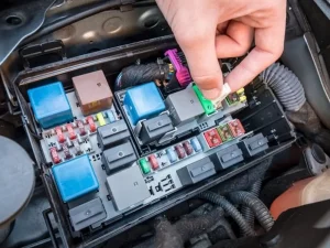
Do you work as an electrician? Or are you a car enthusiast who wants to check the condition of his vehicle’s relay? No matter who you are, knowing how to test an automotive relay is crucial. It helps keep the car’s components running smoothly.
Manufacturers use car relays to control various components, including lights, horns, and wipers. However, if the relays malfunction, those components will also stop working. Are you facing any issues with the element associated with the relay? It’s high time for you to check the relay’s condition.
However, I know that checking and testing those automotive relays is very complex and tedious. But you don’t need to panic—I am here to help you. This guide will give you a stepwise process for testing automotive relays. So, let’s kick things into gear!
Overview of Automotive Relay
Relays are small switches operated with electrical signals. They use little electricity and work as switches to control devices with high electricity consumption. These relays are very common in cars and other vehicles. They can be handy for operating cars’ lights, horns, wipers, and turn signals.
Keep in mind that relays are not limited to the automotive industry. Their usage is common across many industries. Many compressors, refrigeration systems, and air conditioners use them. However, we will only focus on automotive relays. These relays consist of 4 or 5 pins; five are the most common.
These pins have different functions and are noted with numbers. Those numbers include 30, 85, 86, 87, and 87a. You can never check the condition of the relay if you don’t comprehend these pins. Interestingly, each relay consists of a small diagram on its body. This small diagram shows the position of these pins.
Even if you don’t have info, you can understand by seeing the diagram. These relays make or break the connection and turn things on or off. They require a small battery to work. Both AC and DC relays are available. However, cars and other vehicles use 12-volt DC relays. Their operation is very smooth and does not require much electricity.
Understanding of Pins for Relay Testing
Like I said earlier, the car relays have five pins. These pins Are crucial in providing a path for electricity to flow from one point to another. In this way, they play a role in switching devices on and off. Understanding them is paramount for successfully testing these relays. Here is the list of those pin names:
- Pin 30 (known as a common pin)
- Pin 87 (Normally Open Pin)
- Pin 87a (Normally Close Pin)
- Pin 85 and 86 (Coil pins due to their attachment with coil)
If you are confused, don’t worry. You will see a number written on the relay corresponding to each pin. For example, you will see the number 30 with a common pin. Similarly, numbers 85 and 86 are written near the coil pins. The most critical pins, 85 and 86, are connected to the positive and negative terminals of the battery.
These two pins are also known as coil pins. Why? Because these pins are attached to coils that produce magnetic fields. When 85 and 86 pins connect with the battery, magnetism is made due to the coil. So, the pin 30 passes the current and activates the relay. When the relay activates, the current flows to the Normally Open Pin (87).
Anything (horn, light, wiper) attached to pin 87 will start to work. When you disconnect the battery, the coil stops producing magnesium. As a result, the Pin 30 will stop passing the current. So, pin 87 disconnects and breaks, and so does the attached device. The relay becomes inactive. The current can flow to the Normally Closed Pin (87a).
How Do You Test an Automotive or Car Relay?
Do you understand the purpose of those pins’ functionality? Let me briefly overview their operation before I go into the testing process. Understanding the working pins is a must for testing.
- Pin 30: Act as a starting point and pass current through to other pins.
- Pin 85 and 86: Connects to positive and negative terminals of the battery.
- Pin 87 (Normally Open Pin): It becomes active when the battery is connected to coil pins.
- Pin 87a (Normally Closed Pin): Its connection breaks when the battery is connected. It becomes inactive with battery connection, and vice versa.
Got their basics and left no confusion in mind? Let’s dive deep and discuss the step-by-step process of checking automotive relays.
1- Gather Equipment
Checking the car relay requires some tools and equipment. If you don’t have that equipment, you won’t be able to complete the testing process. The good thing is all these automotive test equipment are affordable. You can easily buy them from your nearest shop without breaking your bank. Here is their list:
- Battery source
- Multimeter
- Alligator clips
- Relay diagram
2- Setup Multimeter
In the testing process, the correct setting of the multimeter is paramount. As you know, this is a device that shows you different parameters. Those include voltages, current, continuity, and resistance. During this testing, turn the knob to the resistance setting, indicated by the symbol “Ω.”
Do you know what resistance is? It is a parameter that indicates the flow of current or electricity. Higher resistance means that the flow of current is low and vice versa.
3- Test the Coil (Pins 85 and 86)
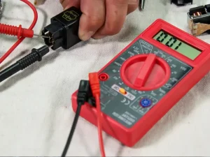
This step technically starts the relay testing process. The multimeter consists of two probes. Connect one probe to pin 85 and the second to pin 86. These two pins are connected to the coil. Now, see the resistance reading on the multimeter. This will tell us whether the coil pins and coil itself are working fine.
Suppose the multimeter shows resistance between 50 and 200 ohms. The current flows, so the coil and pins are fine. Imagine a case where the multimeter shows infinite resistance. This simply indicates that there is no flow of current. So, you should understand there is an issue with the coil or its pins.
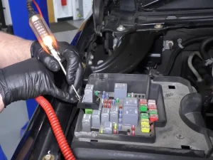
4- Connect Coil to Battery Source
Once you have checked the coil, it is time to check the other pins and see if they are working. You must connect the battery to the coil to ignite some magnetism. But the question is how? Pins 85 and 86 will connect to the positive and negative terminals of the battery. The coil remains attached to these two pins.
Once you connect the pins to the battery terminal, the coil will produce magnetism. Upon connection, you will hear a ‘Click’ sound. This means the system is switched on, and the current passes through pin 30. This pin 30 further passes the current pin 87 (Normally Open Pin). If you don’t hear ‘Click,’ it means there is some issue with the system.
5- Check Continuity Between Pins 30 and 87
Keep the battery connected with pins 85 and 86. During this, the current will continue to flow to pin 30. It is time to check the continuity between pins 30 and 87. Do you know what continuity is? This parameter shows the path for electricity or current flow. If electricity can pass between two points, continuity is there, and vice versa.
During checking continuity, change the setting of the multimeters to continuity from resistance. All the multimeters have small bell-shaped icons for continuity indication. Correct one probe to pin 30 and the second to pin 87. Once you connect the probes, you will hear a beep.
The multimeters will show a zero reading. This indicates electricity has its path to flow between two points or pins, so there is nothing wrong with the relay. On the flip side, if the multimeter does not beep, it indicates no path for electricity flow. The multimeter will show an infinity reading, showing some issues in the relay.
6- Test the Normally Closed Pin (Pin 87a)
If pins 30 and 87 work fine regarding electricity flow, check pin 87a. You must disconnect the battery from pins 85 and 86 for checking pin 87a. Once the battery is disconnected, attach the probe with pin 30 and pin 87a.
Do the multimeters beep and show zero readings? If so, this pine is also working fine. On the contrary, if you don’t hear a beep, it indicates no path for electricity flow. In simple words, there is an issue with pin 87a. Keep in mind to keep the battery disconnected during this step.
Quick Highlight: Follow the process mentioned above to check the condition of the automotive relay. This process can also help check all the DC relays. If you find any issue in any part, it indicates that you should replace the relay with a new one.
What Should You Do if the Automotive Relay is Faulty?
During the testing, you may find issues with any relay component. If you don’t hear the click on the connecting battery with pin 85 or 86, there will be an issue with the coil. If the current does not move from pin 30 to 87, the path of electricity is disturbed. All these things indicate faulty or damaged pins.
In such a case, there are two ways: either repair the faulty part or buy a new relay. Keep in mind that relays are generally inexpensive. However, fixing the damaged part takes a lot of time, and the desired output is also not guaranteed. I suggest you buy a new relay in case of any issues. Using repaired relays can also cause problems in the future.
Frequently Asked Questions
How does relay operate in cars and other vehicles?
The relay works by electrical signals. For example, when you press the horn, the relay gets a signal. As a result, it makes or breaks connections as per its system.
How do mechanics test relays in automotive?
The relay testing relies on the passage of current. The mechanics will check the flow of current at each phase using multimeters. If the flow is optimal, the relay is also in good condition, and vice versa.
What are the uses of relays in cars?
Relay allows many components and devices to work smoothly as per the signals. Those components include horns, wipers, lights, turn signals, etc… The driver just pushes the specific knob specific component, and the relay works the rest.
Conclusion
Auto relays serve their purpose best in cars and vehicles. Their usage has made different car components work smoothly. However, when this relay becomes faulty, it affects the workings of those components.
Imagine a relay connected with a working horn gets faulty. The horn won’t work. Can you drive a car without working horns? So, you need to know the testing process to determine the issue. I have explained the steps of this process in this guide so you can check the issue immediately without waiting for a mechanic.